
The Genius system has been tested with a wide variety of boilers, heat pumps and other heat sources. There are 3 receiver units that can be used to control them: the Single Channel Receiver, the Dual Channel Receiver and the Electric Switch.
General Information
Standard wiring diagrams are provided with the system. To download a copy of the wiring diagrams, visit: https://www.geniushub.co.uk/wiring
The Single Channel Receiver and Dual Channel Receiver are rated to 3A maximum. They can only be used to switch a zone valve or a boiler, not a circulation pump. Controlling a circulation pump will damage the receiver unit and void the warranty.
-
Do not attempt to wire in the boiler controls unless you are 100% sure you know what you are doing. Danger of electric shock! All wiring must conform to BS 7671 (IET Wiring Regulations, current edition). The boiler and the wiring for the boiler controls must be electrically isolated before you start work.
-
To comply with building regulations, every system with a hot water cylinder must have a hard-wired cylinder thermostat to protect against scalding.
Combination Boiler (Single Channel Receiver)
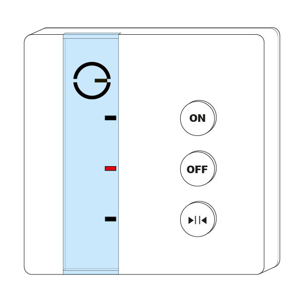
The Single Channel Receiver is included in the Genius Starter Kit, and is most commonly fitted to a combination boiler (for properties without a hot water tank). In many cases you can fit the Single Channel Receiver where the wired house thermostat or boiler programmer was, as it uses a standard backplate. Make sure the wiring is correct for the Single Channel Receiver before fitting it to the backplate.
-
Always make sure the boiler and the wiring for the Single Channel Receiver are electrically isolated before you start work on any wiring.
-
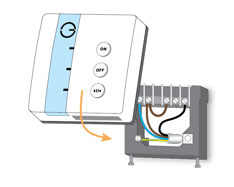
Remove the backplate from the Single Channel Receiver by loosening the 2 screws on the bottom of the unit.
-
Mount the backplate on the wall where the Single Channel Receiver is to be placed, or (if using an existing compatible backplate) remove the front of the existing thermostat/receiver unit. The backplate must be on a flat surface to ensure good contact between the Single Channel Receiver and the backplate.
-
Wire the Single Channel Receiver backplate as shown in the wiring diagrams provided, checking this against the boiler installation manual.
-
Fit the Single Channel Receiver to the backplate by hooking it onto the top of the backplate first, then hinging the unit down. It should hinge easily and rest squarely on the backplate. If it does not attach easily first time, take it off and try again.
-
Tighten the screws underneath the Single Channel Receiver, and check the unit is securely and safely attached to the wall.
In normal operation the Single Channel Receiver shows a single solid light: red when there is no call for heat, and green when it is calling for heat.
-
If there is no existing boiler programmer, the Single Channel Receiver must be wired into the boiler as if it were an external programmer or thermostat. Check the boiler manufacturer's wiring diagrams against the wiring diagrams provided with this installation manual.
-
If you replace the existing house thermostat with the Single Channel Receiver but leave the existing boiler programmer in place (not recommended), the customer must be aware that they will have no control of the boiler if the programmer turns off. In this case the existing programmer must be set to always on (constant) so that the Single Channel Receiver keeps control of the boiler at all times.
-
If you remove the existing wired house thermostat from the control circuit (recommended), it must also be removed from the boiler wiring centre, otherwise the Single Channel Receiver will not have control over the boiler.
System Boiler (Dual Channel Receiver)
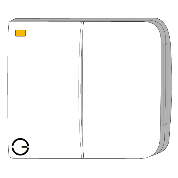
The Dual Channel Receiver is included in the Genius Starter Kit + Hot Water, and is most commonly fitted to a system boiler (for properties with a hot water tank). The existing programmer must be replaced with the Dual Channel Receiver to control both the heating and the hot water. Make sure the wiring is correct for the Dual Channel Receiver before fitting it to the backplate.
-
Always make sure the boiler and the wiring for the Dual Channel Receiver are electrically isolated before you start work on any wiring.
-
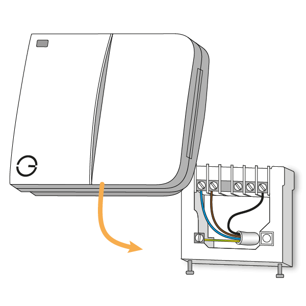
Remove the backplate from the Dual Channel Receiver by loosening the 2 screws on the bottom of the unit.
-
Mount the backplate on the wall where the Dual Channel Receiver is to be placed, or (if using an existing compatible backplate) remove the front of the existing programmer/receiver unit. The backplate must be on a flat surface to ensure good contact between the Dual Channel Receiver and the backplate.
-
Wire the Dual Channel Receiver backplate as shown in the wiring diagrams provided, checking this against the boiler installation manual.
-
Fit the Dual Channel Receiver to the backplate by hooking it onto the top of the backplate first, then hinging the unit down. It should hinge easily and rest squarely on the backplate. If it does not attach easily first time, take it off and try again.
-
Tighten the screws underneath the Dual Channel Receiver, and check the unit is securely and safely attached to the wall.
In normal operation the Dual Channel Receiver shows a solid amber light, which means it is connected to the system. To check whether a channel is on, hold down that channel's button: the light at the top-left will show green for 2 seconds if the channel is on.
-
If there is no existing boiler programmer, the Dual Channel Receiver must be wired into the boiler as if it were an external programmer. Check the boiler manufacturer's wiring diagrams against the wiring diagrams provided with this installation manual.
-
If you remove the existing wired house thermostat from the control circuit (recommended), it must also be removed from the wiring centre, otherwise the Dual Channel Receiver will not have control over the heating.
-
Inside the door of the Dual Channel Receiver are 2 labels showing which button controls which part of the system. When wiring the Dual Channel Receiver, check that the wiring matches these labels.
Hot Water Time & Temperature addon (Electric Switch)
The Hot Water Time & Temperature addon is an Electric Switch with a Temperature Probe (Floor/Tank), which measures the temperature of the hot water tank. The Electric Switch is wired into the same fused spur as the zone valve or immersion heater it controls, near the hot water tank. The end of the Temperature Probe goes into the tank's pocket, or under the tank's insulation.
If the hot water tank has a backup immersion heater, this can be wired to the Electric Switch's output, so you can control heating the hot water with the immersion heater as well as the boiler.
The Temperature Probe must never be pulled out of, or removed from, the Electric Switch.
-
Always make sure the boiler, immersion heater and the wiring for the Electric Switch are electrically isolated before you start work on any wiring.
-
Locate the existing cylinder thermostat on the hot water tank.
-
If the cylinder thermostat's pocket is accessible, insert the Temperature Probe (Floor/Tank) into this pocket.
-
If it is not available, attach the Temperature Probe to the outside of the tank (under the insulation) using thermal paste, so that it gets an accurate water temperature reading and has good contact with the tank.
-
-
Break out the relevant section of a 1-gang pattress for the wiring (allowing for the Temperature Probe to exit the pattress if needed), and fix the pattress to the wall. We recommend a 40mm pattress.
-
Pull through the relevant wiring, leaving plenty of spare.
-
Wire in the Electric Switch as shown in the wiring diagrams provided, checking this against the relevant installation manual (e.g. for the immersion heater).
-
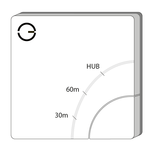
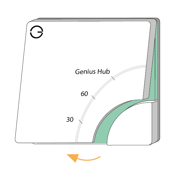
Remove the front cover of the Electric Switch to expose the screw holes. To remove the cover, place a flat-bladed screwdriver into the gap underneath the Electric Switch and lever downwards.
-
Fit the Electric Switch into the pattress, making sure there are no trapped wires. Screw it in using standard pattress screws, and check the unit is securely and safely attached to the wall. Re-attach the front cover, starting at the top.
In normal operation there are no lights when the unit is not heating, and a red light next to 'HUB' when it is heating.
-
The water in a hot water tank stratifies, so the temperature measured depends on where the probe is placed on the tank. We recommend using the location of the existing cylinder thermostat, or a pocket built into the hot water tank. For more information, see the installation manual provided with the hot water tank.
-
The existing cylinder thermostat should be set above the temperature required in the app, and above 60°C to protect against legionella.
-
Use appropriate wiring in accordance with BS 7671 (current edition).
-
The Electric Switch is rated to 13A and must not be wired to an immersion heater with a higher rating. Doing so will damage the Electric Switch and void the warranty.